MMB103
The MegaMiniBoard103
| Copyright: | Copyright 2001 Dean Hall. All rights reserved. |
|---|---|
| Author: | Dean Hall |
| Date: | 2001/12/06 |
| Status: | 2007/07/11: No more work will be done on the MMB103, but it is still in use. |
Introduction
My robot interests involve keeping things small while still exposing the maximum amount of flexibility. The very first microcontroller board I used was Fred Martin's Miniboard.
This board wasn't much larger than a credit card, but four boards networked together made the digital control system for a six legged walking robot that I worked on as a computer engineering student.
Since then, I have wanted to design a microcontroller board of my own. When I saw the specs of the Atmel ATmega103 8-bit RISC, I started designing the board straight away. During the year it took me to complete the circuit board, procure parts and build and test the MMB103, GCC support for Atmel AVR and ATmega microcontrollers was announced (free C!) and Larry Barello announced AvrX, his multitasking kernel for the AVR/ATmega series of controllers (free kernel!).
MMB103 Features
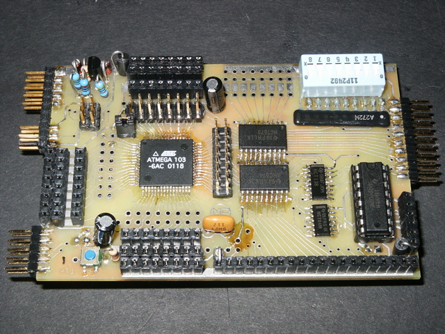
The MMB103 was designed with robotics in mind, but I also made as many things as open ended as possible. For instance, all of the '103's pins are available; but I also sent two of them directly to the motor driver as PWM signals. Here are the features of the microcontroller:
ATmega103
- 128KB Flash, 4KB SRAM, 4KB EEPROM
- 8-channel, 10-bit ADC; one analog comparator
- UART, SPI communication interfaces
- Two 8-bit timers, one 16-bit timer
- Three hardware PWM sources
- 5V in-system programming
The ATmega103 has a lot going for it. Most notably an upgrade path. Atmel recently announced the ATmega128 -- a pin-compatible replacement for the 103. This means the MMB103 board will also accommodate the new chip.
MMB103
The processor alone does not a good robot board make. I have used my own robotics experience and incorporated good ideas from people throughout the net to determine the features of the MMB. Here they are:
- Feature-packed ATmega103 microcontroller, all pins accessible
- In-system programming via PonyProg
- 8-channel analog input, 8-channel digital input, 8-bit DIP switch input
- 20-pin data bus expansion port with predecoded address selects
- 2 port, 1A motor driver with direct PWM in locked-antiphase configuration
- 20/16/14-pin (graphic) LCD connector
- UART with level converter on board
- SPI header for serial networking
Programming the Flash memory in a microcontroller is usually a hassle. However, Atmel has incorporated in-system programming into all of its AVR/ATmega processors. This allows the user to reprogram the chips quite easily. I chose to use a circuit designed by Claudio Lanconelli, the creator of the PonyProg system.
Using this circuit, the MMB103 can be (re)programmed directly from a PC's serial port! The only equipment needed is a common DB-9 to 5x2 header connector. A high-voltage programming source is NOT required.
The 8-channels of analog input go directly to the 103's ADC. However, the 8-channels of digital input, the 8-bit DIP switch input, and the LCD are all latched to the 103's data bus pins, so they don't consume any extra pins!
The 2 port motor driver uses two of the 103's PWM signals to provide variable-speed control of any motor up to 1A. Two enable signals are also latched from the data bus to provide brake/coast ability to the motors. I chose the common TI SN754410 as the motor driver (free samples!). The motor driver is hardwired in the locked-antiphase configuration. I got this idea from Larry Barello who does a good job of explaining the concept.
The short story is that the motor driver's Enable pin is always asserted while the 103's PWM signal is connected to the motor driver's Direction pin. This holds the motor at zero rotation when the PWM is at 50% duty cycle (equal amount of forward and reverse current). As the duty cycle increases from 50% the motors spin in one direction; and as the duty cycle decreases from 50% the motors spin in the other direction. One advantage of locked-antiphase is observed when a robot drives down a ramp: the PWM method used by the Handyboard lets the robot increase in velocity as it decends the ramp; the locked-antiphase method absorbs that kinetic energy back into the battery and constrains the speed of the robot.
The LCD connector is very flexible due to the two data latches connected to the data bus. The first 14 pins are for the common 2x16 through 4x20 LCD character displays. I've also seen some 20-pin graphics LCD displays that share the same pinout for pins 1-14. Unfortunately, B.G. Micro sold out of them long ago (I only have one left and I'm keeping it). Regardless, this port can be programmed to accommodate most small LCD displays.
A MAX233 level converter allows the 103's UART to talk to a PC's serial port. With the 103 clocked at 4 MHz, a 19200bps connection works reliably with only 0.2% error. If you're worried that you don't see it in the picture, the MAX233 is hidden on the back of the board.
I am a big proponent of SPI. I've used it to network 4 HC11's and I'm using it here. SPI provides a serial digital network at high speeds (4Mbps on board, 1Mbps at 3 meters over twisted pair). I will use this to allow multiple MMB103s to communicate. I am going to use the SNAP protocol to allow the kernel to send and receive messages over the network (kernel-level multiprocessor multi-tasking!).
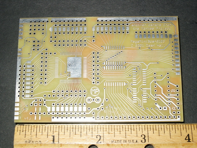
The MMB103 Circuit Board
I originally drew the MMB103 circuit board layout using the free software layout program ExpressPCB. I did this so that I could post the single .sch file and others could use that file and have the board fabricated for themselves. I ordered my first three prototype boards through ExpressPCB and was very pleased with the quick turnaround, low price and acceptable quality.
It took me over a month to draw the board and another month to verify the traces because the layout and schematic tool (from another vendor) were not integrated. Even after the long verification, I accidently drew three trace defects. I knew an integrated schematic/layout tool would alleviate this pain, but I thought ExpressPCB would be easier for Joe Public. Larry Barello convinced me that it would be better to use an integrated tool and suggested Eagle. I had read of Eagle but had never used it. I have redrawn most the MMB103's schematics using Eagle (it takes a little while to get used to it) and I plan to use it for the next/final version of the MMB103 layout.
The Software
The number one reason I chose the Atmel AVR/ATmega family of processors was the free C compiler, avr-gcc. avr-gcc runs on Mac OS X, Linux and Win32 systems. The number two reason for choosing the AVR/ATmega was Larry Barello's AvrX multitasking kernel.
AvrX is a tiny multi-threading, priority scheduler that includes semaphores, inter-thread communication, software timers, and more stuff that isn't particularly relevant right now. AvrX is written in assembly, but is called from C just like any other C function. Let me say that AvrX has everything you would expect from a commercial quality 8-bit embedded kernel.
Currently, I am writing a simple C library for the MMB103 that will expose an API for all the major features of the board. Once the simple library is complete, I intend to write a more complex library that exposes a similar API, but uses AvrX for more complex features.
The end goal is to create a software system that runs across multiple boards (each with different peripherals) allowing the peripherals and robot behaviors to coordinate and cooperate over the SPI network:
- Board B has just activated Behavior X which prints a message on the LCD display connected to Board A.
- Board C has a Behavior Y which just received sensor information from Board A and must suppress Behavior X on Board B.
- Dream on!
Conclusion
The MMB103 is a robot controller board that has numerous hardware features and plenty of software opportunities. When the hardware is debugged and the software libraries are in a beta quality stage, I plan to release the MMB103 project to the robot community. Along the way, I might upgrade to the pin-compatible ATmega128, yielding the MMB128.
My robot, Snaggletooth, will be the first robot to sport the MMB103. I hope to have Snaggletooth operational and competing at the next DPRG Roborama.